

Selecting the appropriate 3D printing process is a critical step in ensuring part quality, functional performance, and cost-efficiency. Yet with a growing number of technologies available—each offering different strengths, limitations, and material compatibility—engineers and product teams often struggle to make the right choice early in the development cycle.
This article offers a practical framework to help you align process selection with your project’s technical requirements and production goals, minimizing trial-and-error and accelerating time to result.
Choosing a 3D printing process isn’t just about machine capabilities. It’s about aligning technology with design intent, performance goals, and production realities. Before comparing specs or cost, you need a clear understanding of what your part must achieve and under what constraints it must be manufactured.
Below are six critical factors that should drive your decision-making.
Start with what your part needs to do. Is it meant to support weight, absorb impact, or flex under load? Or is it primarily a visual prototype with no structural function?
Aesthetics often play a larger role than expected, especially for consumer-facing products, enclosures, or presentation models.
Different processes support different material classes—thermoplastics, photopolymers, elastomers, or metals—and not all materials are interchangeable across technologies.
Ask:
For example:
Understanding your production needs early on helps avoid cost and capacity issues later.
Not all processes can hold the same level of accuracy or fine detail, especially on small features, internal channels, or sharp transitions.
Also consider warping, shrinkage, and tolerance stacking—especially for multi-part assemblies.
Cost is always a factor, but it should be evaluated comprehensively.
Beyond just the raw material or machine rate, consider:
A lower-cost process may lead to higher downstream costs if surface finishing, part rework, or structural compromise become necessary.
Here’s a simplified overview of how different factors influence the ideal process selection:
| Factor | FDM | SLA | SLS | MJF | DMLS |
|---|---|---|---|---|---|
| Ideal Use Case | Basic prototypes, housings | High-detail visual models | Functional parts, complex geometries | Small-batch production, functional prototypes | Precision metal parts |
| Design Complexity (Overhangs, Internal Channels) | Limited – support needed | Limited – support needed | Excellent – no support needed | Excellent – fine features are possible | Good, but overhangs need support |
| Assembly Compatibility | Moderate – shrinkage possible | Excellent – tight tolerances | High–dimensional stability | High – good repeatability | Excellent – CNC-level precision |
| Post-Processing Complexity | Low – manual cleanup | High–curing & support removal | Medium – powder removal | Medium – powder & finish | High–thermal stress relief, machining |
| Recommended for Batch Production | ✕ | ✕ | ✔ | ✔ | ✕ |
| Certifiable Materials (e.g., FDA, Biocompatible) | Some available | Medical/dental resins | Industrial nylons (PA11, PA12) | Some certified nylons | Titanium, SS, Inconel, etc., with certifications |
| Typical Layer Thickness | 100–300 μm | 25–100 μm | 100–120 μm | 80–100 μm | 20–60 μm |
Note: The right process is the one that balances trade-offs based on your project’s unique combination of needs.
Understanding the differences between 3D printing processes is essential before making any decision. While the underlying principles of additive manufacturing are similar—layer-by-layer construction—the equipment, materials, and outcomes vary significantly across technologies.
Here’s a practical breakdown of the five most widely used 3D printing processes, their typical applications, and where each method fits best.
Stereolithography (SLA) is one of the earliest and most precise 3D printing technologies. It builds parts by selectively curing liquid photopolymer resin with a laser, layer by layer, achieving exceptional detail and surface smoothness. SLA is widely used when high resolution and aesthetic quality are prioritized, especially in medical modeling, product design, and mold prototyping.
Engineering Insight:
SLA is ideal for visually accurate parts where fine detail and finish matter more than strength. It’s not suitable for load-bearing components or environments with heat, impact, or prolonged UV exposure.
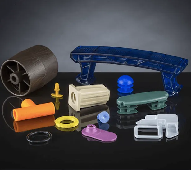
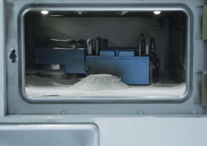
Selective Laser Sintering (SLS) is a powder-bed fusion process that uses a laser to sinter fine nylon particles into solid parts. Unlike SLA or FDM, SLS does not require support structures—the unsintered powder itself acts as a self-supporting medium during printing. This makes it particularly effective for producing complex, interlocking, or nested geometries.
SLS materials, most commonly PA12 and PA11, offer strong mechanical performance and chemical resistance, making this process well-suited for functional testing and end-use production. Parts printed with SLS are durable and dimensionally stable, even under load or in challenging environments.
Engineering Insight:
SLS is ideal when you need production-quality performance in plastic, without tooling. It’s a go-to solution for functional parts where design freedom and mechanical strength are essential.
Multi Jet Fusion (MJF) is a powder-based 3D printing process developed by HP that builds parts by selectively depositing fusing and detailing agents onto a bed of nylon powder, then fusing them with infrared energy. Unlike SLS, which uses a laser, MJF relies on an inkjet-style printhead and uniform heating system, resulting in faster print cycles and excellent consistency across builds.
MJF produces parts with reliable mechanical properties, high dimensional accuracy, and fine feature detail, making it well-suited for functional prototypes and end-use plastic components. It is especially efficient for small- to medium-sized batch production, thanks to its speed and nesting capability.
Engineering Insight:
MJF is an excellent choice when you need a balance between print speed, functional performance, and part appearance. It’s often preferred over SLS when tight dimensional tolerances and efficient throughput are priorities.
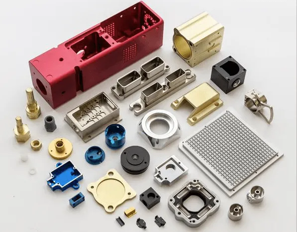
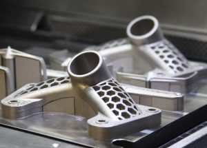
Direct Metal Laser Sintering (DMLS), also known as Selective Laser Melting (SLM), is an advanced powder-bed fusion process that produces fully dense metal parts directly from digital CAD files. A high-powered laser fuses thin layers of metal powder in a controlled atmosphere, layer by layer, to form solid, high-performance components.
DMLS is capable of producing complex geometries that are difficult or impossible to achieve through traditional machining, including internal cooling channels, lattice structures, and conformal features. Parts printed with DMLS exhibit near-isotropic mechanical properties and can be post-processed via heat treatment and CNC finishing for even tighter tolerances.
Engineering Insight:
DMLS is the technology of choice when part strength, material properties, and geometric complexity cannot be compromised. It replaces traditional machining in cases where design freedom, weight reduction, and customization are critical.
After reviewing the main types, let’s explore how to choose wisely!
Understanding each 3D printing method is useful, but translating that knowledge into the right decision for your specific project requires structure. A methodical selection process can reduce trial-and-error, lower costs, and improve part outcomes, especially when time and accuracy matter.
Here’s a practical framework to help you align your design goals with the most appropriate 3D printing process.
Start with the most fundamental question:
What do you need this part to do?
Clarifying the part’s role early helps you rule out overengineering—or underbuilding—for its intended use.
Now translate your design intent into measurable specifications.
Consider:
Capturing both engineering and appearance criteria ensures you won’t miss performance-critical details—or underestimate visual expectations.
Production scale and delivery speed are often overlooked until they become problems. Think ahead:
Technologies like FDM or SLA work well for one-offs, while SLS and MJF offer better value for small batches. DMLS, meanwhile, is viable mainly when high-performance or regulatory-grade metal parts are justified.
Once your functional, visual, and production needs are clear, compare them against the capabilities of each 3D printing process.
Here’s a quick reference table to guide your selection:
| Project Type | Recommended Processes |
|---|---|
| Basic fit or concept prototype | FDM, SLA |
| Visual presentation model | SLA, PolyJet |
| Functional plastic prototype | SLS, MJF |
| Durable end-use plastic part | SLS, MJF |
| Custom jig or fixture | FDM, MJF |
| Transparent or fine-detail model | SLA |
| Flexible or elastomeric part | SLS (TPU), MJF (TPU), PolyJet (rubber-like) |
| Regulatory-grade medical prototype | SLA (biocompatible resin), DMLS |
| Lightweight or high-stress metal part | DMLS, SLM |
This table is a starting point—not a substitute for testing—but it helps you narrow down viable directions early.
Once you’ve selected a process, don’t skip validation—especially if the part is new, critical, or has tight tolerances.
Even small prototype adjustments can reveal issues early and avoid costly revisions at production scale.
Final Thought: Great design isn’t just about what you build—it’s about how you choose to build it. A structured selection process turns 3D printing from a tool into a strategic advantage.
Even experienced engineers can make costly missteps when selecting a 3D printing process, especially when under pressure to deliver fast, cut costs, or prototype early. Understanding common pitfalls helps you avoid design rework, unexpected delays, or underperforming parts.
Here are four mistakes we often see—and how to avoid them.
SLA produces excellent surface quality and fine detail, but its photopolymer materials tend to be brittle. Relying on SLA for parts that require impact resistance, mechanical load, or repeated handling can lead to cracking, deformation, or early failure.
Quick Fix: Use SLA for visual models only. For mechanical strength, switch to SLS or MJF, which offer better durability and isotropic properties.
Some processes require extensive finishing—support removal, sanding, dyeing, curing, or heat treatment. Ignoring these steps when budgeting or planning lead times often leads to unexpected labor costs and delivery delays.
Quick Fix: Factor post-processing time and effort into your decision from the start. If minimal finishing is preferred, FDM (basic), SLS (no supports), or MJF (cleaner break-off edges) are better options.
SLA and PolyJet offer high-resolution surfaces, but their parts may warp or shrink over time, especially under stress or environmental exposure. Choosing a technology solely based on appearance can compromise performance in functional applications.
Quick Fix: Balance aesthetics with mechanical reliability. If both are critical, consider MJF for strong parts with acceptable surface finish, or post-process SLS parts for appearance improvements.
Orientation affects strength, surface quality, and accuracy. Poor orientation or ignoring support strategies can lead to weak layers, visible marks, or distorted geometries, especially in FDM and SLA prints.
Quick Fix: Work with your print provider or DfAM specialist to define optimal build orientation and support strategy. For complex geometries, processes like SLS and MJF are more forgiving due to powder-bed support.
Tip for Engineers: Always validate your process choice with a small-batch or prototype run before scaling. This helps reveal issues with material behavior, tolerances, or downstream assembly early on.
Choosing the right 3D printing process is not about picking the most advanced technology—it’s about aligning your part’s requirements with what each process does best. Whether you’re building a quick prototype, a functional assembly, or a production-grade part, understanding materials, tolerances, geometry, and production volume helps guide that choice with clarity.
By applying a structured selection process and avoiding common missteps, you can make smarter, faster decisions—and deliver better results.
Not sure which process fits your part? Our team can help you validate your design and material match before printing. Contact us today to get expert advice.